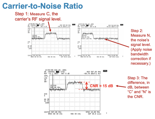
64-QAM lower than Analog video on the downstream? 64-QAM lower than 16-QAM on the upstream? Why is a 6.4 MHz channel lower than a 3.2 MHz DOCSIS channel? Someone said there is math for all of this, but man QAM is getting me down!
These questions come up in every lecture I give on DOCSIS. Why do QAM measurements show up at different levels on a spectrum analyzer than analog measurements. What’s more, why do QAM signals of different bandwidth have different levels? Some of the questions have straight forward math – this is easy to explain and for you to remember. However some of the differences in level between analog video signals or continuous wave (CW) signals and the digital QAM signals when measured on a spectrum analyzer or headend monitoring system become much more complex. I shy away form answering them in lectures because it involves a good bit more explanation – which will be covered in this article.
First let us start off with the simple and move to the complex. A term used in science and engineering is Power Spectral Density or PSD. This is a big word for how much energy a signal contains. Think of your garden hose. When you turn it on a respectable amount of water comes out. Enough that you can fill a bucket of water in a couple of minutes. That is sort of like the amount of RF energy that a CW signal or the analog video carrier has. Now think of a fire hose on full with two firemen holding on to it. That will fill the bucket of water up while at the same time shooting it through your neighbors front door. That is similar to a 3.2 MHz wide QAM signal – it has more RF energy than the CW signal because it is – a fatter pipe. So we can lower the level of the QAM signal and still have the same RF energy as the CW signal or Analog video. Taking one more step, the 6.4 MHz signal in the upstream or 6 MHz QAM in the downstream is like a water main. That will shoot the bucket through your neighbors front door, out the back and into the VW Microbus he has had sitting there rusting for years. So we can throttle back that power even more.
The Power Spectral Density (PSD) between any two channels can easily be determined as a logarithmic function. For instance, if one channel is 1 MHz wide and the other channel is 2 MHz, the following formula is used to determine the PSD difference or correction factor between the two channels:
Hey, how about that! You should be familiar with 3.01 dB. That is the half power bandwidth rule and printed on most splitters. So a signal that is twice as wide as another signal has twice as much power or 3.01 dB more power, which is twice as much in dB.
Now if think of the DOCSIS upstream and look at the two available options we have 3.2 MHz and 6.4 MHz. What should the difference in power be? Just about 3 dB because 6.4 MHz is twice as wide as 3.2 MHz. We’ll use the correction factor equation to verify:
Exactly as we expected!
Now its time to calculate the difference between the QAM signals and the CW or video carrier signal. We will assume the measurement is being made on a spectrum analyzer or equivalent device that such as a headend monitoring system. A spectrum analyzer treats a CW as a peak voltage signal and a QAM as a noise signal, so there are two correction factors that must be used. The following two items are frequently over-looked and result in a 2 dB error in headend setup: [list type=”list2″]
- Under-response due to voltage envelope detection (add 1.05 dB) or log-scale response (add 2.51 dB). For almost all CATV equipment you will find logarithmic scales, so a correction factor of 2.51 dB will be added.
- Over-response due to the ratio of the equivalent noise bandwidth to the –3 dB bandwidth (subtract 0.52 dB). This 0.52 dB negative correction factor is due to the fact that the Resolution Bandwidth (RBW) Filter is not ideal and rolls-off at the edges.[/list]
The total correction for 2.51 dB – 0.52 dB = 1.99 dB. If you have not been including this as part of your headend correction factor now you know where it comes from.
Next you must add a correction factor for the bandwidth of the QAM “noise” channel against whatever resolution bandwidth is set on the spectrum analyzer. The formula this is similar to the one used earlier:
Using a RBW of 300 kHz (which is typical) and a QAM bandwidth of 3.2 MHz, the corrections factor is as follows:
So here is an example to create the correction factor for a 3.2 MHz 16-QAM channel (this would give you the offset in dB from the CW):
Correction Factor (dB) = 1.99 + 10.28 = 12.27 dB
So the 3.2MHz QAM channel should be 12.27 dB below the analog signal as measured on a spectrum analyzer or headend monitoring system if the RBW is 300 kHz.
There is not be any difference for different modulation, i.e. 16-, 32-, 64- or 256-QAM, but what will make a difference is going to a 6 MHz or 6.4 MHz channel bandwidth. Look at the example below:
Correction Factor (dB) =1.99 dB + 13.29 dB = 15.28 dB
From the previous equation: 15.28 – 12.27 = 3.01 dB Wow! How about that. There is your 3 dB drop when you increase from 3.2 MHz to 6.4 MHz. Once again, twice the bandwidth holds true for twice the power.
I recommend that you read the Agilent AN 1303 Application Note which is quite informative on how spectrum analyzers make these measurements. PathTrak and other products follow the same methodology. I have the app note on my website because it is so valuable (and sometimes hard to find).
Upcoming events can be seen under Broadband Events. Previous events can be seen under the blog.
- If you watch on youtube please hit the subscribe button!
- Let us know what you think and remember to share!
- You can find slides at the bottom of the page and some on slideshare.
- Find out about events or articles by following us on Twitter, LinkedIn or Facebook too.
Also available on iTunes, Google Podcasts, Spotify, vurbl see podcasts “get your tech on”.


Just want to say “thank you” for your blog posts. I’m going through them now and agreed it’s often somewhat over simplified but that’s the point so good job!
Thanks for the feedback Ektel. Your post is welcome on my site. You have some good content on your blog.
-Brady
Hi, I’ve found your article searching the web for a calculation I want to make and it really really helped me a lot – great article!
I just want to ask you one question: what formula one should use to determine the PSD difference or correction factor between two channels with different QAM modulation (lets say 3.2 MHz wide 16QAM signal and 6.4 MHz wide 32QAM signal).
Thank you.
Hi Bobi,
Your question was answered during the G+Hangout. You can watch it here or download it on iTunes. https://volpefirm.com/load-balancing-docsis-3-1-episode-7/
Thanks,
Mia